Skema Rangkaian Elektronika-Circuit-Wiring Diagram
UM3561 IC Sound Effect Generator

This circuit uses a UM3561 IC to produce four different sound effects.UM3561 IC Sound Effect Generator Circuit Notes Nothing too complicated here. The IC produces all the sound effects, the output at Pin 3 being amplified by the transistor. A 64 ohm loudspeaker can be substituted in place of the 56 ohm resistor and 8 ohm loudspeaker. The...
Current Limiting Power Supply Diagram

Description This is a 1-amp variable-voltage PSU. It adjusts from about 3v to 24v: and has the added feature that you can limit the maximum output current. This is invaluable when (for example) you power-up a project for the first time or soak-test a piece of equipment. Notes SW3 is the on/off switch. It also lets you choose between the...
Current Limiter Regulated Power Supply

Current Limiter Regulated Power Supply CircuitThe Current Limiter Regulated Power Supply has been especially designed for current-hungry ham radio transceivers. It delivers safely around 20Amps at 13.8V. For lower currents, a separate current limiting output, capable of 15ma up to a total of 20A has been added.The power transformer should...
LT1300 Solar Powered Power Supply

LT1300 Solar Powered Power Supply This architecture was generated as allotment of a alien acclimate base project. One of the requirements of the architecture is that it accept a solar-powered accumulation with rechargeable batteries. This architecture is based on a photovoltaic arrangement accessible from Radio Shack alleged a BatterySAVER...
Rangkaian Subwoofer 22watts Menggunakan TDA1516

22 Watts Mini Subwoofer Circuit TDA1516 with Adjustable FrequencyThe subwoofer is a subwoofer or a apostle to carbon low frequencies, addict of 20 Hz to 150 Hz cyberbanking ambit diagram beneath shows the capacity of a arrangement of the capital amplifier TDA1516 22 watt in 4 ohm car subwoofer driver. This accessory is advised for an absolute...
TLC271 Simple Solar Panel Circuit
simple solar panel shunt regulator by TLC271Solar console regulators appear in abounding flavors. The plainest acidity is the simple on-off blazon blow regulator. It has the advantage of simplicity, acutely baby ability dissipation, low cost, aerial reliability, but in barter for these advantages one has to acquire that the voltage on the...
RANGKAIAN ALARAM KEBAKARAN NE555

Fire alarm circuit using LDR (Light Depending Resistor) as light sensor. It warns the user against fire accidents. It relies on the smoke that is produced in the event of a fire. When this smoke passes between a LED and an LDR, the amount of light falling on the LDR decreases. This causes the resistance of LDR to increase and the voltage...
Rangkaian Frost Detector Temperature Sensor Circuit

To know whether it is freezing you only need to measure the temperature. This has to be done accurately, of course, and therefore we need to choose a temperature sensor that we have some confidence in. The choice has again been made for a type that we have already used in many previous Elektor circuits, the LM35CZ (-40 to 110 °C). This sensor...
Rangkaian S-video Converter Circuit

With the astonishingly rapid growth in the market for flat-screen TVs and high-definition TV, many CRT television sets have been consigned to the attic, even though many of them were still working perfectly and could have been used as spare sets in a bedroom or another room, for example. Although all current flat-screen receivers have very...
Radiator Fan Circuit For Kawasaki ZRX1200

Kawasaki ZRX1200 Radiator Fan Circuit DiagramTo inspect and service the 2001 to 2006 Kawasaki ZRX1200 R/S radiator fan system, do the following: * Remove fuel tank. * Disconnect the 2 pin connector from radiator fan switch. * Using an auxiliary wire, connect the radiator fan switch leads of the main harness side. * Turn the ignition...
Nikon Coolpix 4500 Digital Camera Service Manual

Nikon Coolpix 4500 This manual will guide the user to troubleshooting, service and repair NIkon coolpix 4500 unit VAA11901 (J), VAA11902 (U), VAA11903 (EP), VAA11904 (CN). Assembling: Joint unit, Finder unit, Lens unit, Flash unit, CA1, CA2, Lens cover, CA3, PW1, SY1, TB2, Battery holder, Lens unit and body unit, LCD, C/F Card cover, Front...
Sony KV-32S40 CRT Television Service Manual

Sony KV-32S40 CRT Television This manual is divided into four major sections. We recommend that you carefully review the contents of each section in the order presented to ensure that you fully understand the operation of your new TV. Sony KV-32S40 CRT Television service manual AA-2D CHASSIS with chassis number SCC-S07A-A contain several...
Automatic Solar Tracking System CIRCUIT
AUTOMATIC SOLAR TRACKER starts following the SUN right from dawn, throughout the day, till evening, and starts all over again from dawn next day. On cloudy weathers, it remains still and catches the SUN again as it slips out of clouds. It does all this automatically, employs cheap and inexpensive components, and is very accurate.Let us see...
RANGKAIAN POWER SUPPLY SWITCHING 5V

The switching regulator which used LM2575-5.0 in this page. You can make the stable voltage by using the 3 terminal regulator like LM317. However, because the output electric current and the inputted electric current are the same approximately, the difference between the input electric power (The input voltage x The input electric current)...
NE555 Rain Alarm Circuit

Rain Alarm using NE555 SchematicThis circuit gives out an alarm when its sensor is wetted by water. A 555 astable multivibrator is used here which gives a tone of about 1kHz upon detecting water. The sensor when wetted by water completes the circuit and makes the 555 oscillate at about 1kHz.The sensor is also shown in the circuit diagram....
Rangkaian Fm Transmitter 1W
Components List:T1 = T2 = T3 = BF199T4 = 2N4427, BLX65, 2N3866, 2N3553L1 = rf choke (20 turns, 0.2mm on ferrite core, 0.3mm)L2 = 4 t, 0.7mm, 4mmL3 = 6 t, 0.8mm, 6mm, at first turn from T3L4 = 10 t, 0.2mm over ferrite coreL5 = 7 t, 0.8mm, 6mmL6 = 4 t, 1mm, 8mm, 10mm longFirst build the oscillator stage and the buffer, power it up and trim...
Skema Rangkaian Long Range FM transmitter
The power output of most of these circuits are very low because no power amplifier stages were incorporated.The transmitter circuit described here has an extra RF power amplifier stage, after the oscillator stage, to raise the power output to 200-250 milliwatts. With a good matching 50-ohm ground plane antenna or multi-element Yagi antenna,...
Rangkaian TDA2030 Power Amplifer

This is an audio power amplifier circuit using only a single chip and few passive components, that you can build 8-14 Watt audio power amplifier using TDA2030 chip. This is the figure of the circuit.When you use 4 ohm speaker then you get 14 Watt output power, and around 8 Watt if you use 8 ohm loudspeaker. Make sure the 100n and 100u capacitor...
High Voltage Pulse Generator Electronic Circuit
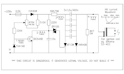
This circuit generates high voltage pulses from 230vac line voltage. The drive end's swing comparator circuit is invented by the creator of this page. The work end is derived from stroboscope trig supply circuit. All line voltage using circuits are inherently dangerous, and this is particulary so. Do not build it. Specifications and schematic...
LM723 Peak Level Indicator Circuit

This circuit is a circuit diagram inspection signal sound level or Peak Level Indicator circuit using LM723. Usually we are often led IC LM723 or UA723 do come to use, the DC voltage regulator. But for this circuit, building a circuit can check the sound level signal. When I saw changes in the structure of integrated circuits. The following...
LOW-COST HEARING AID Schematic

Commercially available hearing aids are quite costly. Here is an inexpensive hearing aid circuit that uses just four transistors and a few passive components. On moving power switch S to ‘on’ position, the condenser microphone detects the sound signal, which is amplified by transistors T1 and T2. Now the amplified signal passes through coupling...